Crankshaft — removal and installation Ford F150
Removal
Note: The crankshaft can be removed only after the engine has been removed from the vehicle. It’s assumed that the driveplate, crankshaft pulley, timing chains, oil pan, oil pump body, oil pump drive chain (2.7L engines), crankshaft sensor ring, oil filter, engine block skirt stiffener (2.7L engines), main cap support brace (3.5L engines) and piston/connecting rod assemblies have already been removed. The rear main oil seal retainer must be unbolted and separated from the block before proceeding with crankshaft removal.
Checking crankshaft endplay with a dial indicator
1. Before the crankshaft is removed, measure the endplay. Mount a dial indicator with the indicator in line with the crankshaft and just touching the end of the crankshaft as shown (see illustration).
2. Pry the crankshaft all the way to the rear and zero the dial indicator. Next, pry the crankshaft to the front as far as possible and check the reading on the dial indicator. The distance traveled is the endplay. A typical crankshaft endplay will fall between 0.003 to 0.010 inch (0.076 to 0.254 mm). If it is greater than that, check the crankshaft thrust surfaces for wear after it’s removed. If no wear is evident, new main bearings should correct the endplay.
- On V6 engines, the thrust bearings are installed at the number 4 crankshaft saddle and bearing cap.
- On 5.0L V8 engines, the thrust bearings are installed at number 5 crankshaft saddle and bearing cap.
Note: When installing thrust washers, make sure the grooves in the washer face the crankshaft.
Checking the crankshaft endplay with feeler gauges at the thrust bearing journal
3. If a dial indicator isn’t available, feeler gauges can be used. Gently pry the crankshaft all the way to the front of the engine. Slip feeler gauges between the crankshaft and the front face of the thrust bearing or washer to determine the clearance (see illustration).
4. On 2.7L engines, remove the engine block stiffener bolts, then insert a small pry bar between the four pry pads on the block and stiffener and pry the stiffener up to break the seal. Remove the stiffener then remove the stiffener-to-block seal from the stiffener.
5. On 3.3L and 3.5L engines, remove the main bearing cap support brace bolts, in reverse order of installation sequence (see illustration 10.38) and remove the support brace.
6. Loosen the main bearing cap bolts 1/4-turn at a time each, until they can be removed by hand. On V8 models, follow the reverse of the tightening sequence (see illustrations 21d and 21e).
7. Remove the main bearing caps. Gently tap the main bearing cap with a soft-face hammer. Pull the main bearing cap straight up and off the cylinder block. Try not to drop the bearing inserts if they come out with the assembly.
8. Carefully lift the crankshaft out of the engine. It may be a good idea to have an assistant available, since the crankshaft is quite heavy and awkward to handle. With the bearing inserts in place inside the engine block and main bearing caps, reinstall the main bearing cap assembly onto the engine block and tighten the bolts finger-tight. Make sure the caps are in the exact order they were removed with the arrow pointing toward the front (timing chain and front cover) of the engine.
Installation
9. Crankshaft installation is the first step in engine reassembly. It’s assumed at this point that the engine block and crankshaft have been cleaned, inspected and repaired or reconditioned.
10. Position the engine block with the bottom facing up.
11. Remove the mounting bolts and lift off the main bearing caps.
12. If they’re still in place, remove the original bearing inserts from the block and from the main bearing cap assembly. Wipe the bearing surfaces of the block and main bearing cap assembly with a clean, lint-free cloth. They must be kept spotlessly clean. This is critical for determining the correct bearing oil clearance.
Main bearing oil clearance check
13. Without mixing them up, clean the back sides of the new upper main bearing inserts (with grooves and oil holes) and lay one in each main bearing saddle in the engine block. Each upper bearing (engine block) has an oil groove and oil hole in it. The thrust washer or thrust bearing insert must be installed in the correct location. Clean the back sides of the lower main bearing inserts and lay them in the corresponding location in the main bearing cap assembly. Make sure the tab on the bearing insert fits into the recess in the block or main bearing cap assembly.
Caution: The oil holes in the block must
line up with the oil holes in the engine block inserts.
Note: The oil grooves in the thrust washers must face toward the front of the engine. Caution: Do not hammer the bearing insert into place and don’t nick or gouge the bearing faces. DO NOT apply any lubrication at this time.
14. Clean the faces of the bearing inserts in the block and the crankshaft main bearing journals with a clean, lint-free cloth.
15. Check or clean the oil holes in the crankshaft, as any dirt here can go only one way — straight through the new bearings.
16. Once you’re certain the crankshaft is clean, carefully lay it in position in the cylinder block.
17. Before the crankshaft can be permanently installed, the main bearing oil clearance must be checked.
18. Cut several strips of the appropriate size of Plastigage. They must be slightly shorter than the width of the main bearing journal.
Place the Plastigage onto the crankshaft bearing journal as shown
19. Place one piece on each crankshaft main bearing journal, parallel with the journal axis (see illustration).
20. Clean the faces of the bearing inserts in the main bearing cap assembly. Hold the bearing inserts in place and install the assembly onto the crankshaft and cylinder block. DO NOT disturb the Plastigage.
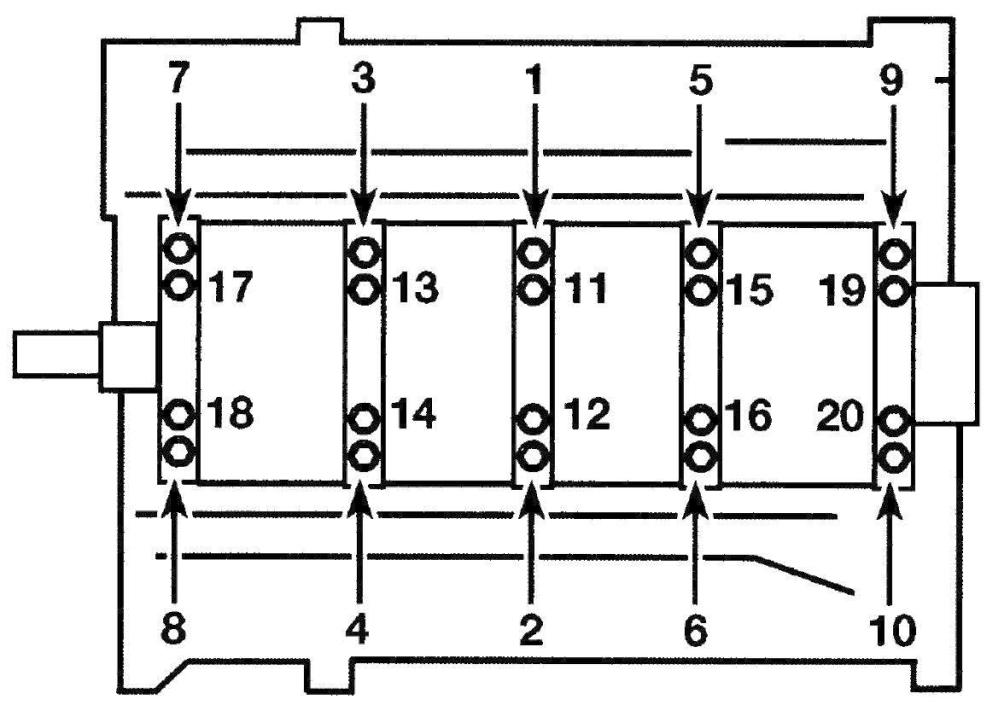
Main bearing cap bolt tightening sequence (2.7L V6 engines)
Main cap bolt tightening sequence — 3.5L V6 engines
Side bolt tightening sequence — 3.5L V6 engines
Main cap bolt tightening sequence — 5.0L V8 engines
Side bolt tightening sequence — 5.0L V8 engines
21. Apply clean engine oil to all bolt threads prior to installation, then install all bolts finger-tight. Tighten the bearing cap assembly bolts in the sequence shown (see illustrations) pro¬gressing in steps, to the torque listed in this Chapter’s Specifications. DO NOT rotate the crankshaft at any time during this operation.
Note: V8 engines and 3.3U3.5L V6 engines are equipped with side bolts. The 2.7L en¬gine is equipped with a block skirt stiffener and 3.3U3.5L engines are equipped with a main cap support brace, but it isn’t necessary to install them for the oil clearance check.
22. Remove the bolts in the reverse order of the tightening sequence and carefully lift the main bearing caps straight up and off the block. Do not disturb the Plastigage or rotate the crankshaft. If the main bearing cap assembly is difficult to remove, tap it gently from side-to-side with a soft-face hammer to loosen it.
Use the scale on the Plastigage package to determine the bearing oil clearance — be sure to measure the widest part of the Plastigage and use the correct scale; it comes with both standard and metric scales
23. Compare the width of the crushed Plastigage on each journal to the scale printed on the Plastigage envelope to determine the main bearing oil clearance (see illustration). Check with an automotive machine shop for the crankshaft endplay service limits.
24. If the clearance is not as specified, the bearing inserts may be the wrong size (which means different ones will be required). Before deciding if different inserts are needed, make sure that no dirt or oil was between the bearing inserts and the cap assembly or block when the clearance was measured. If the Plastigage was wider at one end than the other, the crankshaft journal may be tapered. If the clearance still exceeds the limit specified, the bearing insert(s) will have to be replaced with an undersize bearing insert(s). Caution: When installing a new crankshaft always install a standard bearing insert set.
25. Carefully scrape all traces of the Plastigage material off the main bearing journals and/or the bearing insert faces. Be sure to remove all residue from the oil holes. Use your fingernail or the edge of a plastic card -don’t nick or scratch the bearing faces.
Final installation
26. Carefully lift the crankshaft out of the cylinder block.
27. Clean the bearing insert faces in the cylinder block, then apply a thin, uniform layer of moly-base grease or engine assembly lube to each of the bearing surfaces. Be sure to coat the thrust faces as well as the journal face of the thrust bearing.
28. Make sure the crankshaft journals are clean, then lay the crankshaft back in place in the cylinder block.
29. Clean the bearing insert faces and apply the same lubricant to them. Clean the engine block and the main bearing caps thoroughly. The surfaces must be free of oil residue.
30. On V6 engines, apply a bead of RTV sealant to the engine block on the rear main bearing cap parting line. Be sure the main bearing cap is installed within four minutes after the RTV sealant is applied.
31. Prior to installation, apply clean engine oil to all bolt threads wiping off any excess, then install all bolts finger-tight.
32. Tighten the main bearing caps following the correct torque sequence (see illustrations 21a through 21e). Tighten the bolts to the torque listed in this Chapter’s Specifications.
33. Recheck the crankshaft endplay with a feeler gauge or a dial indicator. The endplay should be correct if the crankshaft thrust faces aren’t worn or damaged and if new bearings have been installed.
34. Rotate the crankshaft a number of times by hand to check for any obvious binding. It should rotate with a running torque of 50 inlbs or less. If the running torque is too high, correct the problem at this time.
35. On 2.7L engines, clean the engine block stiffener mounting surface then install a new oil seal. Apply a 3/16-inch bead of RTV sealant to the engine block skirt stiffener seal surfaces and install the stiffener over the crankshaft assembly and on to the block.
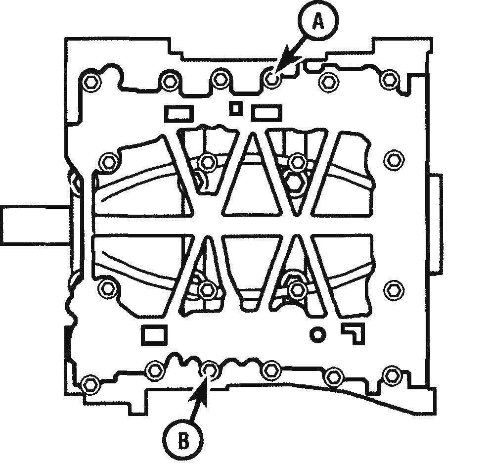
Tighten bolts A and B then align the engine block stiffener to the engine block
36. On 2.7L engines, install the stiffener mounting bolts hand tight, then tighten bolts A and B (see illustration) to the torque listed this Chapter’s Specifications. Use a straightedge and align the rear face of the engine block skirt stiffener with the rear face of the engine block. It must be flush or up to 0.01 inch behind the face of the engine block. Use the straightedge and align the machined left side face of the engine block skirt stiffener with the machined left side faces of the engine block. It must be flush or up to 0.01 inch behind the machined face on the side of the engine block.
Engine block skirt stiffener bolt tightening sequence — 2.7L V6 engines
37. On 2.7L engines, once the alignment is within specifications, tighten the bolts in sequence (see illustration) to the torque listed this Chapter’s Specifications.
Caution: The engine block stiffener must be installed and tightened to the minimum specifications within 10 minutes or the stiffener must be removed and the RTV sealant cleaned off and new sealant applied.
Main cap support brace bolt tightening sequence — 3.5L V6 engines
38. On 3.3L and 3.5L engines, install the main cap support brace and tighten the bolts in sequence (see illustration) to the torque listed this Chapter’s Specifications.
39. Install the new rear main oil seal (see V6 engines or V8 engines).


