Balljoints — check and replacement Ford F150
Check
1. Inspect the upper and lower balljoints for looseness whenever the vehicle is raised for any reason. You can check the balljoints with the suspension assembled as follows.
2. Raise the vehicle and support it securely on jackstands.
3. Wipe the balljoints clean and inspect the seals for cuts and tears. If a balljoint seal is damaged, replace the balljoint.
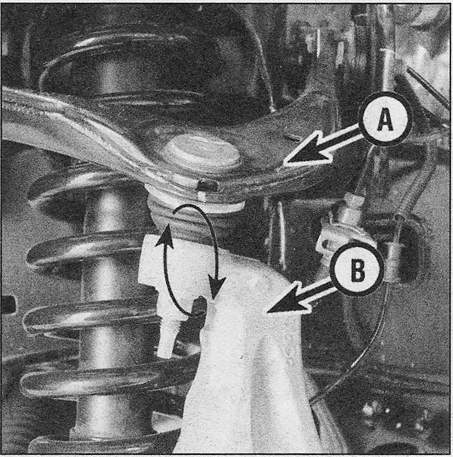
4. To check the upper balljoint, grab the upper control arm near the balljoint and attempt to move the arm up and down. Any noticeable play between the upper control arm and the steering knuckle indicates the need to replace the upper balljoint (see illustration).
.4 Grab the upper control arm (A) and attempt to move it up and down while checking for any movement between the control arm and the steering knuckle (B)
5. To check the lower balljoint, attempt to move the wheel up and down while checking for play between the lower control arm and the steering knuckle. Any noticeable play indicates the need to replace the balljoint.
Upper ball joint — removal and installation
6. The upper balljoints on these models are not serviceable. If the balljoint must be replaced, the control arm and balljoint must be replaced as a single assembly (see Upper control arm – removal and installation) for removal and installation procedures for the upper control arm.
Lower ball joint — removal and installation
7. Apply the parking brake. Loosen the wheel lug nuts and raise the front of the vehicle. Support it securely on jackstands and remove the wheel.
8. Remove the steering knuckle (see Steering knuckle – removal and installation).
9. Remove and discard the lower ball joint snap-ring.
10. Using a balljoint removal socket and press clamp (available at specialty tool retailers and some auto parts stores), press the balljoint out of the lower control arm from the top out through the bottom.
11. To install, use the balljoint installing socket and press clamp. Press the balljoint into place (from the underside of the control arm) making sure the balljoint presses firmly into the control arm and exposes the snap-ring groove on the opposite side of the control arm.
12. Install the new snap-ring.
13. Installation is the reverse of removal.
