Check the engine drivebelt Ford F150
1. The drivebelt(s) is located at the front of the engine and plays an important role in the overall operation of the vehicle and its components. Due to its function and material make-up, the drivebelt is prone to failure after a period of time and should be inspected and replaced periodically to prevent major engine damage.
2. 2.7L V6 models are equipped with a single automatically adjusted serpentine drivebelt, which is used to drive all of the accessory components such as the alternator, water pump and air conditioning compressor. 3.3L Duratec, 3.5L V6 models (turbo and non-turbo) are equipped with two drivebelts — a main accessory serpentine belt that drives the alternator and water pump and is automatically adjusted, and an air conditioning compressor drivebelt that doesn’t use a tensioner. V8 models are equipped with two automatically adjusted serpentine drivebelts — a main belt that is used to drive the alternator and water pump, and another that drives the air conditioning compressor.
Inspection
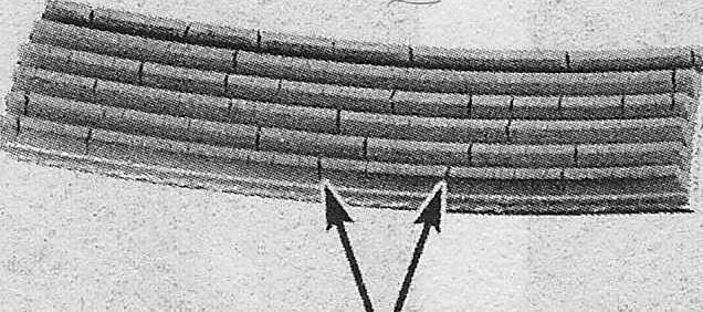
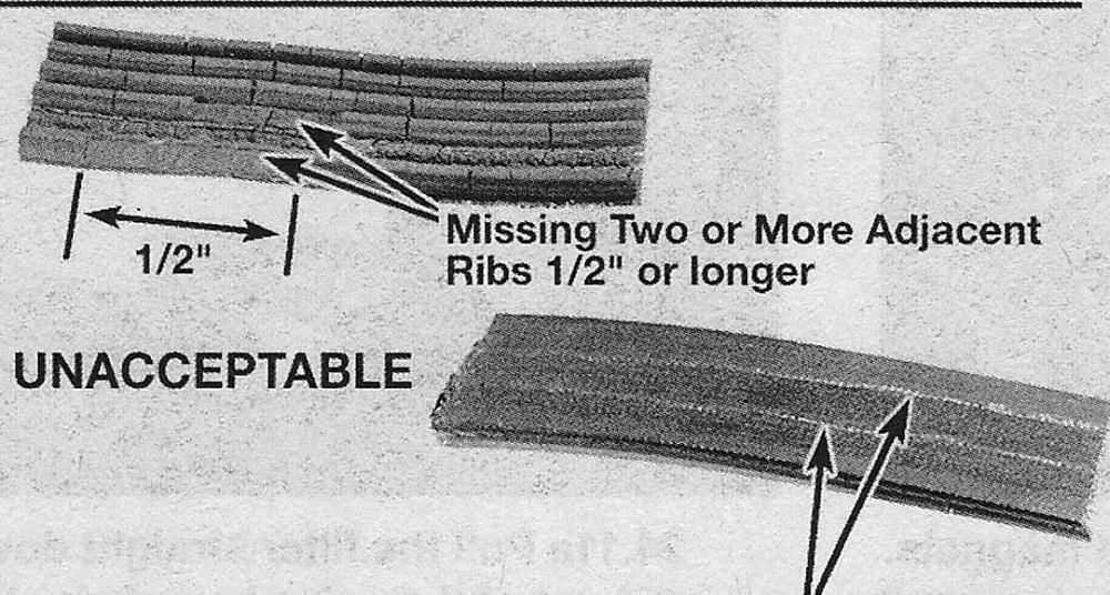
3. With the engine off, open the hood and locate the drivebelt at the front of the engine. Using your fingers (and a flashlight, if necessary), move along the belts checking for cracks and separation of the belt plies. Also check for fraying and glazing, which gives the belt a shiny appearance. Both sides of each belt should be inspected, which means you will have to twist the belt to check the underside.
ACCEPTABLE Cracks Running Across «V» Portions of Belt
Cracks Running Parallel to «V» Portions of Belt
Small cracks in the underside of a V-ribbed belt are acceptable — lengthwise cracks, or missing pieces that cause the belt to make noise, are cause for replacement
4. Check the ribs on the underside of the belt. They should all be the same depth, with none of the surface uneven.
5. The tension of the belt is automatically adjusted by the belt tensioner and does not require any adjustments. The tensioner can be checked with the belt removed, by moving the tensioner from its release position through a full stroke and back to make sure there is no excessive sticking, grabbing or binding, and to make sure there is tension on the drivebelt tensioner spring at all times. Check the drive-belt wear (see Steps 3 and 4).
Replacement
6. Raise the vehicle and support it securely on jackstands, then remove the engine under cover, if accessing the drivebelt from below. To access the drivebelt tensioner(s) from above, remove the air intake duct and housing, or any other intake ducting that may interfere with drivebelt access, where equipped (see Chapter 4).
Note: it is easier to access the tensioner from under the vehicle.
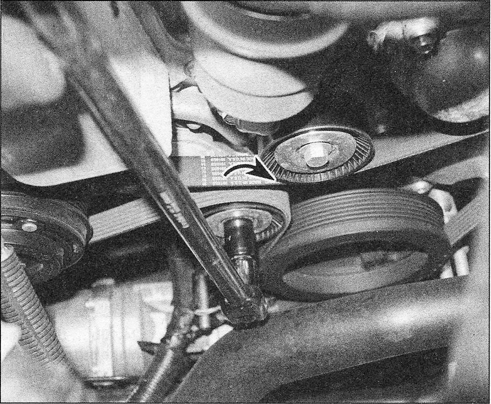
Rotate the tensioner arm to relieve belt tension — 2.7L V6 engine shown
Accessory drivebelt(s)
7. To replace the accessory drivebelt, rotate the tensioner to relieve the tension on the belt, then slip the belt off of an accessible pulley. Once the belt is loose, allow the tensioner to slowly come to rest at its stopping point.On all models, place a socket with a breaker bar on the tensioner pulley center bolt. On V6 models, rotate the tensioner clockwise and on V8 models rotate the tensioner counterclockwise.
8. V8 models have a second rear (inner) air conditioning compressor drivebelt which has a square hole in the tensioner arm that will accept a 3/8-inch drive breaker bar, rotate the tensioner clockwise to relieve the tension on the belt.
9. Remove the belt from the remaining auxiliary components.
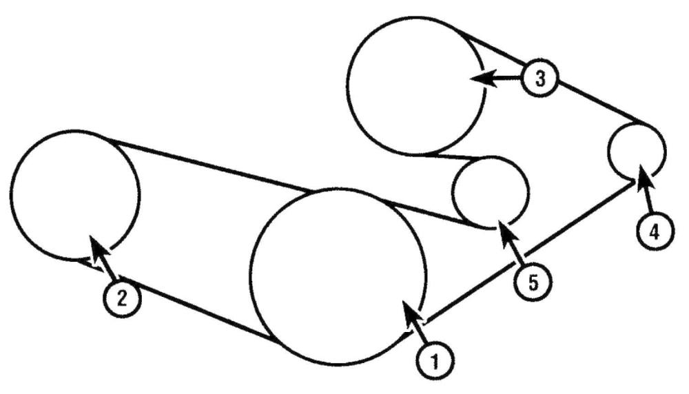
The drivebelt routing schematic for 2.7L V6 models
1. Crankshaft pulley;
2. Tensioner and pulley pulley;
3. Air conditioning;
4. Idler pulley;
5. Water pump;
6. Alternator pulley;
The drivebelt routing schematic for 3.5L V6
1. Crankshaft pulley;
2. Air conditioning;
3. Water pump compressor;
4. Alternator;
5. Tensioner and pulley
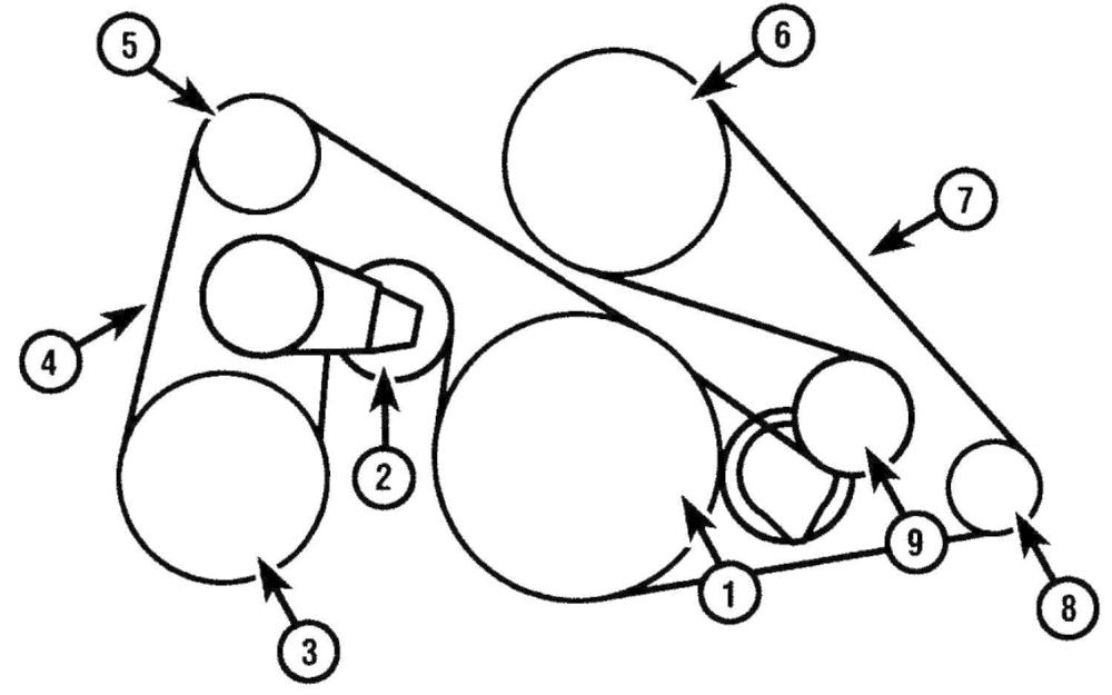
The drivebelt routing schematic for 5.0L V8 models
1. Crankshaft pulley;
2. Tensioner and pulley (rear belt);
3. Air conditioning compressor;
4. Rear belt;
5. Idler pulley;
6. Water pump;
7. Front belt;
8. Alternator;
9. Tensioner and pulley (front belt);
10. Route the new belt loosely over the various pulleys, then rotate the tensioner to allow the belt to be installed. Slowly release the belt tensioner when the belt is fitted onto all the pulleys. Make sure the belt fits properly into the pulley grooves — it must be completely engaged.
Note: Most models have a drivebelt routing decal on the upper radiator panel to help during drivebelt installation.
3.3L V6 and 3.5L V6 air conditioning compressor drivebelt
11. Remove the accessory drivebelt (see Steps 7 through 9).
12. Remove the engine splash shield/under cover.
13. Using a pair of diagonal cutting pliers, cut the air conditioning belt to remove it.
Note: Some tool manufacturers make air conditioning compressor belt removal tools that can remove the belt without cutting it off. We only recommend using this type of tool if the belt if relatively new and will be reused. Always check the belt for damage after the removal process.
14. Place one end of the new belt behind the crankshaft pulley, and the other end onto the compressor pulley, making sure the belt is fully seated in the pulley grooves.
15. Place part of the belt onto the top of the crankshaft pulley grooves, letting the rest of the belt toward the bottom of the crankshaft pulley hang/fold inward.
16. At this stage, the belt should be placed evenly onto the compressor pulley and part way onto the top of the crank pulley. While holding the belt in place at the top of the crank pulley, use a cable tie to hold the belt in place at the top crankshaft grooves.
17. Rotate the crankshaft pulley clockwise with a socket and ratchet, which should lift the belt onto the crankshaft pulley grooves.
Warning: DO NOT crank the engine with the starter during this process! Rotate the engine by hand only.
18. The remainder of installation is the reverse of removal. Make sure the belt is even with the pulley grooves.
Tensioner
19. Remove the accessory drivebelt(s) (see Steps 7 through 9).
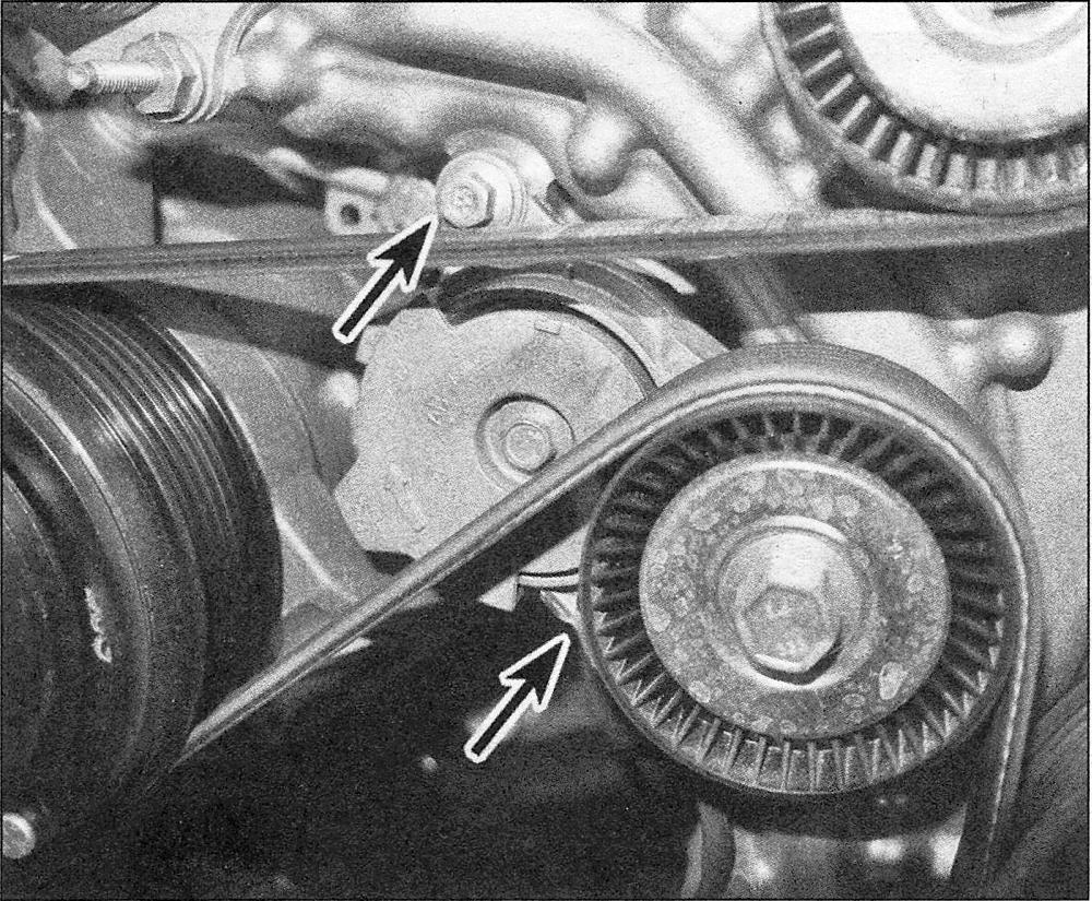
Location of the tensioner mounting bolts — 2.7L V6 engine shown, other models similar
20. Remove the tensioner mounting bolt(s) and remove the tensioner.
Note: V8 models use a single mounting bolt for each tensioner and V6 models use two tensioner mounting bolts.
21. Install the tensioner and tighten the mounting bolts to the torque listed in this Chapter’s Specifications.
22. Installation is the reverse of removal
