Camshafts and tappets/roller followers and lash adjusters — removal and installation Ford F150
Caution: These engines are difficult to work on and require some special tools. On any procedure involving the timing chains, the Steps must be read carefully and disassembly must proceed using the special tools, otherwise damage to the engine will result.
Caution: Because this is an «interference»engine design, if the timing chain has broken, there will be damage to the valves (and possibly the pistons) and will require removal of the cylinder heads.
Caution: The timing system is complex. Severe engine damage will occur if you make any mistakes. Do not attempt this procedure unless you are highly experienced with this type of repair. If you are at all unsure of your abilities, consult an expert. Double-check all your work and be sure everything is correct before you attempt to start the engine.
Caution: 2.7L and 3.5L turbocharged models are equipped with Direct Injection (DI) and a high-pressure fuel pump. Fuel pressure in the high-pressure system on Direct Injection (DI) systems is under extremely high pressure. Be sure to correctly perform the fuel pressure relief procedure prior to servicing any of the high-pressure fuel system components to prevent injury (see Fuel pressure relief procedure).
Note: 3.3L Duratec, 3.5L Duratec and 2016 and earlier 3.5L EcoBoost engines use solid tappets (cam followers). 2.7L and 2017 3.5L EcoBoost engines use roller followers and hydraulic lash adjusters.
Removal
Note: If you’re removing the camshafts from both sides, remove the right (passenger’s) side first
2.7L engines and 2017 and later 3.5L turbocharged engines
1. Raise the vehicle and support it securely on jackstands.
2. Relieve the fuel pressure (see Fuel and exhaust systems).
3. Disconnect the cable from the negative battery terminal (see Engine electrical systems)
4. Remove the high-pressure fuel pump drive (see Fuel and exhaust systems) when removing the right-side camshafts or, on 2.7L models, the brake vacuum pump (see Brakes) when removing the left-side camshafts.
5. Refer to Timing chains and sprockets – removal and installation and remove the timing chain(s) and camshaft VCT units.
6. Loosen then remove the front «megacap» mounting bolts and mega-cap first. Caution: The front camshaft mega-cap must be removed first then the remaining camshaft bearing caps or possible engine damage may occur.
7. Loosen the camshaft caps mounting bolts and remove the caps.
Caution: Keep the caps in order and don’t mix them up.
8. Remove the camshafts from the cylinder head(s).
9. Remove the roller followers and lash adjusters as assemblies. Keep the followers and lash adjusters in order and don’t mix them up.
10. Remove the spring clips on the camshaft roller followers and separate the lash adjusters from the rockers.
Caution: If the original components are to be reinstalled, they must be installed in their original locations
2016 and earlier 3.5L turbocharged engines and all 3.3L/3.5L non-turbocharged engines
11. Before removing the camshafts, check the valve clearances (see Valve clearance – check and adjustment).
12. Refer to Timing chains and sprockets – removal and installation and remove the timings chain and camshaft VCT units also the tensioner holding tool and camshaft holding tools.
13. Loosen the camshaft caps and «mega-cap» mounting bolts and remove the caps. Remove the camshafts from the cylinder head.
Caution: Keep the caps in order and don’t mix them up.
14. When removing the right-side camshafts on 3.5L turbocharged models, remove the brake vacuum pump (see Brakes).
15. With the camshafts removed, the tappets can be removed using a magnet. Caution: They must be stored in an egg carton or other divided and marked container, so they can be reinstalled to their original locations during reassembly.
Inspection
16. After the camshafts have been removed, clean them with solvent, then inspect the bearing journals for uneven wear and pitting. If the journals are damaged, the bearing saddles in the cylinder heads and caps are probably damaged as well. The head and camshaft caps will have to be replaced.
17. Measure the bearing journals with a micrometer and compare to the Specifications in this Chapter to determine whether they are excessively worn or out-of-round.
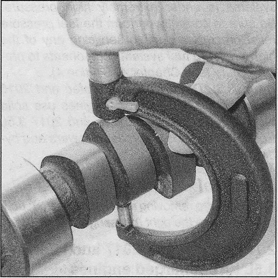
Lobe lift can be obtained by measuring camshaft lobe height…
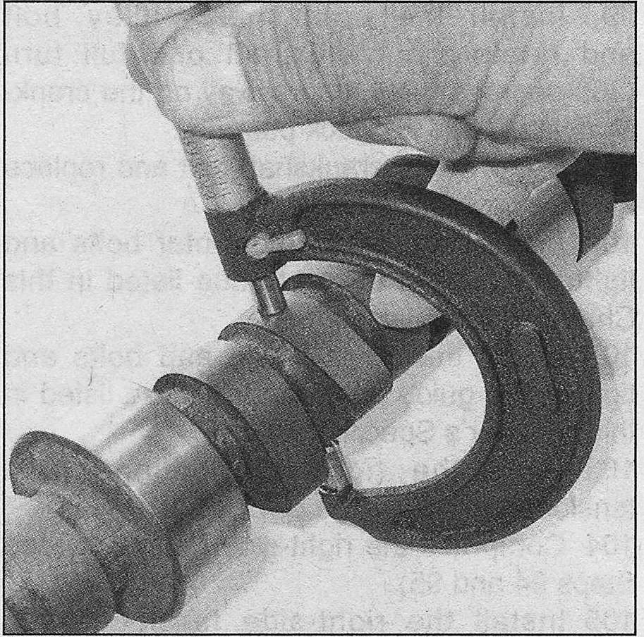
… and by measuring the camshaft base circle — the difference between the two measurements equals lobe lift
18. Measure the camshaft lobe height and the base circle. The difference between the two measurements is the lobe lift (lobe height — base circle = lobe lift). Record this figure for future reference and repeat the check on the remaining camshaft lobes. Compare the results to the values listed in this Chapter’s Specifications.
19. Inspect the camshaft lobes for heat discoloration, score marks, chipped areas, pitting and uneven wear. If the lobes are in good condition and if the lobe lift measurements are as specified, you can reuse the camshafts.
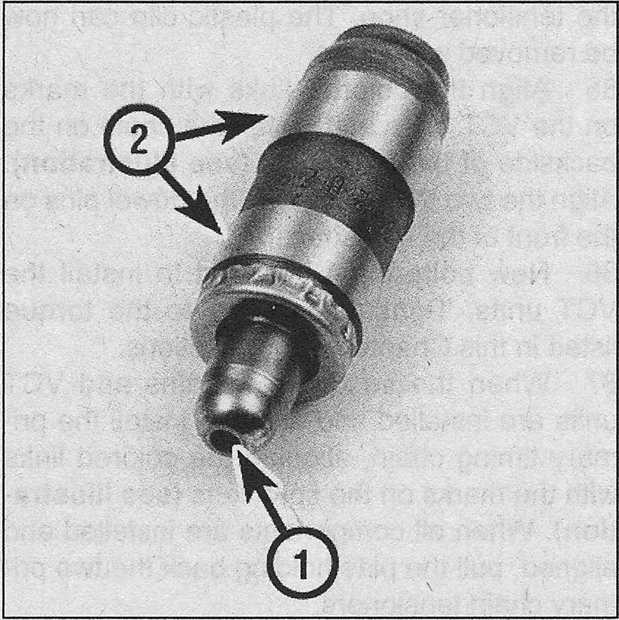
Inspect the lash adjuster for signs of excessive wear or damage, such as pitting, scoring or signs of overheating (bluing or discoloration) — the areas of wear are the rocker arm pivot point (1) and the side surfaces where the lifter body contacts the cylinder head bore (2)
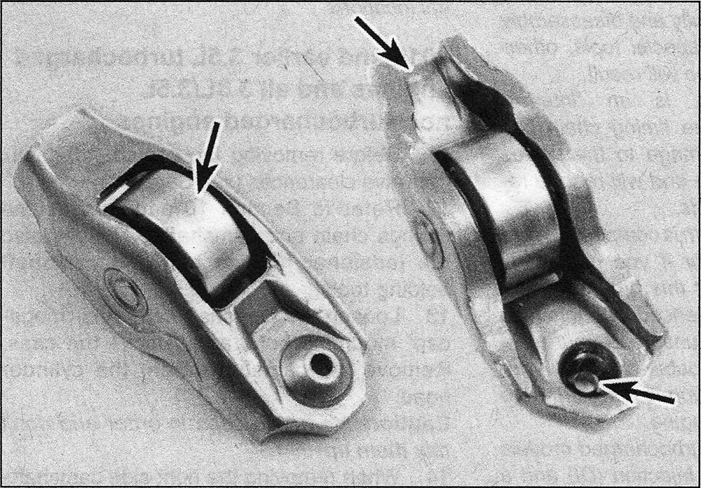
Check the rocker arm roller, the valve stem contact point and lash adjuster contact point
20. On 2.7L and 2017 3.5L turbocharged engines, check the lash adjusters and roller followers for wear.
Installation
2.7L engines and 2017 and later 3.5L turbocharged engines
21. On 2.7L engines, insert the lash adjuster onto the spring clips on the camshaft roller followers, then lubricate them with oil and install them into their original locations. On 3.5L turbocharged engines, lubricate the lash adjusters with oil and install them into their original locations.
Caution: On 2017 and later 3. 5L turbocharged engines, do not install the camshaft roller followers at this time. They will be installed later (see Steps 28 through 31). If the followers are installed before the camshafts caps are tightened, the camshaft caps can become distorted when the camshafts are tightened and cause severe damage to the engine.
22. Lubricate the camshaft bearing journals and cam lobes with moly-based grease or camshaft installation lubricant.
When installing the left (driver’s) side cylinder head camshafts, position the D-slots pins like this — 2.7L engines
When installing the left (driver’s) side cylinder head camshafts, position the D-slots pins like this — 2017 and later 3.5L turbocharged engines
When installing the right (passenger’s) side cylinder head camshafts, position the D-slots pins like this — 2.7L engines
When installing the right (passenger’s) side cylinder head camshafts, position the D-slots pins like this — 2017 and later 3.5L turbocharged engines
23. Position the camshafts in the cylinder head in their neutral positions.
24. Apply a small 1 mm bead of RTV to the rear camshaft cap at the inner corners, then install the camshaft cap and remaining camshaft caps with bolts, loosely tightening the cap bolts at this time.
25. Install the front «mega-cap» and bolts and loosely tighten the mega-cap bolts, at this time.
Left (driver’s) camshaft bearing cap tightening sequence — 2.7L engine
Left (driver’s) camshaft bearing cap tightening sequence — 2017 and later 3.5L turbocharged engines
Right (passenger’s) camshaft bearing cap tightening sequence — 2.7L engine
Right (passenger’s) camshaft bearing cap tightening sequence — 2017 and later 3.5L turbocharged engines
26. Tighten all the camshaft bolts, in sequence, to the torque listed in this Chapter’s Specifications.
27. Install the camshaft holding tools to the left camshafts then install the VCT units (see Timing chains and sprockets – removal and installation).
28. Install the timing chains (see Timing chains and sprockets – removal and installation) but on 3.5L turbocharged models do not install the valve covers.
2017 and later 3.5L turbocharged engine
29. Starting with the front cylinder, rotate the crankshaft pulley clockwise until the cylinder’s camshaft lobes are pointing upwards.
30. Install special service tool 303-1633 and 303-1633-01 over the camshaft and on to the top of the valve springs. Tighten the knob on the tool clockwise to depress the valve and spring.
31. Lubricate the roller follower with clean engine oil then insert the follower, making sure the spring clip on the follower clips onto the lash adjuster. Once the follower and lash adjuster are assembled, rotate the knob on the tool counterclockwise to slowly release the valve and spring.
32. Repeat Steps 29 through 31 for the remaining roller followers.
All models
33. The remaining installation steps are the reverse of removal.
34. Before starting and running the engine, refill the cooling system, change the oil and install new oil filter (see Tune-up and routine maintenance).
Note: After filling the engine with oil, it may take up to 15 minutes for oil to correctly register on the oil dipstick (see Tune-up and routine maintenance).
2016 and earlier 3.5L turbocharged engines and all 3.3L/3.5L non-turbocharged models
35. Rotate the crankshaft counterclockwise and position the keyway in the 9 o’clock position (this is the neutral position).
36. Lubricate the tappets with clean engine oil and reinstall them in their original locations. If any valve clearances were out-ofspecification, replace the tappet(s) with new ones of the proper thickness to achieve the desired clearance.
37. At the front of each camshaft, there are two grooves to hold seals. Obtain new seals and install them in the camshaft grooves.
Note: The split where the ends of each seal come together must face UP (12 o’clock position) on the camshafts when they are installed.
38. Lubricate the camshaft bearing journals and cam lobes with moly-based grease or camshaft installation lubricant.
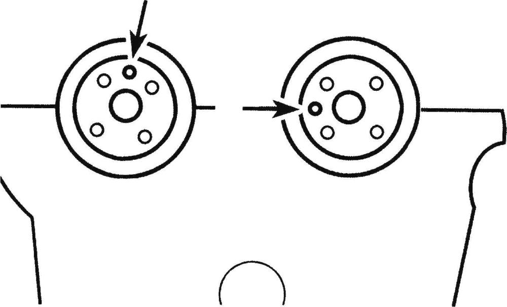
When installing the left (driver’s) side cylinder head camshafts, position the dowel pins like this
When installing the right (passenger’s) side cylinder head camshafts, position the dowel pins like this
39. Position the camshafts in the cylinder head in their neutral positions.
Camshaft bearing cap tightening sequence
40. Install the camshaft bearing caps (in their original locations), and tighten the bolts, in sequence, to the torque listed in this Chapter’s Specifications.
41. Recheck the valve clearances (see Valve clearance – check and adjustment). Since the crankshaft is in the neutral position, the camshafts can be turned without the valves contacting the pistons.
42. Remove the camshaft cap bolts that secure the valvetrain oil tubes. Remove the oil tubes.
Rotate the left (driver’s) side cylinder head camshafts so the dowel pins are positioned like this (TDC position), then install the camshaft holding tool
Rotate the right (passenger’s) side cylinder head camshafts so the dowel pins are positioned like this (TDC position), then install the camshaft holding tool
43. Rotate the camshafts to position the dowel pins in their proper positions for installing the VCT units and timing chains. Install the camshaft holding tools.
44. Rotate the crankshaft clockwise to position the keyway in the 11 o’clock position.
45. Install the VCT units (see Timing chains and sprockets – removal and installation).
46. Install the timing chains (see Timing chains and sprockets – removal and installation).
47. Reinstall the valvetrain oil tubes and tighten the bearing cap bolts to the torque listed in this Chapter’s Specifications.
48. The remaining installation steps are the reverse of removal.
49. Before starting and running the engine, refill the cooling system, change the oil and install new oil filter (see Tune-up and routine maintenance).
