Intake manifold(s) — removal and installation Ford F150
Warning: If you’re working on a 3.3L or 3.5L non-turbocharged engine and are going to be removing the lower intake manifold, relieve the fuel system pressure (see Fuel and exhaust systems).
1. Disconnect the cable from the negative battery terminal (see Battery – disconnection and reconnection).
2. Remove the engine cover.
3. Remove the air filter housing and intake duct (see Fuel and exhaust systems).
2.7L engine
Removal
4. Remove the charge air cooler pipes (see Fuel and exhaust systems).
5. Disconnect the quick-connect fittings to the EVAP purge control valve then remove the purge valve from the intake manifold (see Emissions and engine control systems).
6. Disconnect the quick-connectors for the PCV hose then detach the PCV hose from the valve cover and manifold.
7. Disconnect the engine wiring harness electrical connectors, the MAP sensor electrical connector and retainers for the vacuum lines and wiring harness.
8. Disconnect the electrical connector at the throttle body and unclip the harness from the retainers.
9. Remove the coolant pipe mounting bolts and move the coolant pipe out of the way.
Carefully lift the manifold off of the engine — Do not use a hammer, and once the manifold is off, cover the intake ports of the engine with clean shop rags.
10. Remove the manifold mounting bolts and detach the manifold from the engine.
Installation
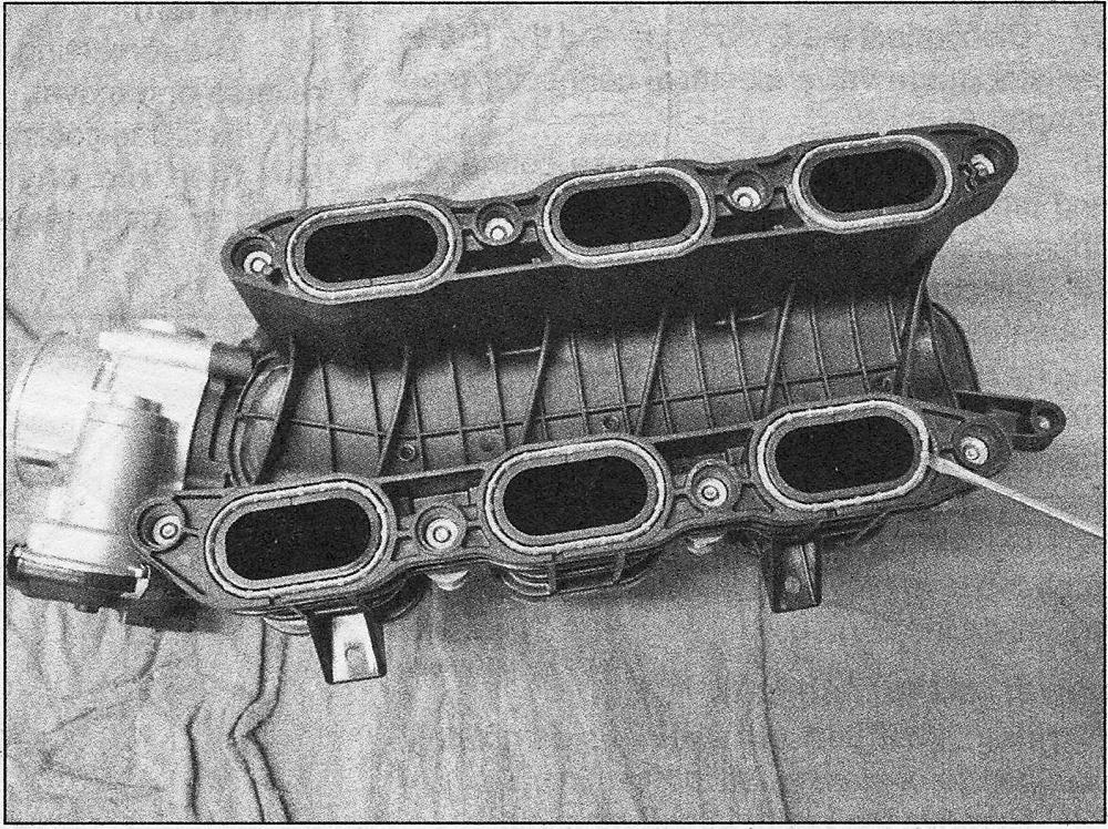
Use a small screwdriver or pick and pull the old gaskets out of the grooves in the intake manifold
11. Remove the old gaskets from the manifold. Clean the manifold and cylinder head mating surfaces.
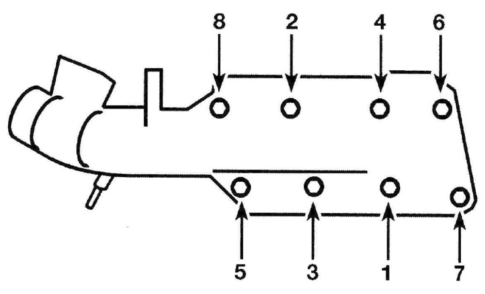
Intake manifold bolt tightening sequence — 2.7L V6 engine
12. Install the new manifold gaskets to the grooves in the manifold. Install the manifold and bolts. Tighten the bolts in the indicated sequence to the torque listed in this Chapter’s Specifications (see illustration).
13. The remainder of the installation is the reverse of removal.
3.3L and 3.5L non-turbocharged engines
Removal
14. If you’re going to be removing the lower intake manifold, relieve the fuel system pressure (if not already done) (see Fuel and exhaust systems).
Upper intake manifold
15. Remove the PCV tube from the manifold. If you’re working on a 3.3L engine, remove the bolts and detach the EGR pipe, transducer, and exhaust manifold tube from the upper intake manifold.
16. Disconnect the electrical connector from the throttle body (see Fuel and exhaust systems).
17. Disconnect the EVAP tube and the EVAP canister purge valve electrical connector (see Emissions and engine control systems).
18. Disconnect the vacuum hose connector and the brake booster vacuum hose from the upper intake manifold.
19. Disconnect the PCV valve hoses from the valve covers and remove them from the engine (see Emissions and engine control systems).
20. Remove the mounting bolts from the upper intake manifold, then lift the upper manifold off of the lower manifold.
21. Cover the air intake passages with a shop towel to prevent tools or debris from falling inside the engine.
Lower intake manifold
Warning: Wait until the engine is completely cool before beginning this procedure.
22. Remove the upper intake manifold.
23. Drain the cooling system (see Tune-up and routine maintenance).
24. Cover the drivebelt with plastic wrap, then remove the thermostat housing (see Cooling, heating and air conditioning systems). Disconnect the heater hose from the manifold.
25. Detach the fuel line from the fuel rail (see Fuel and exhaust systems) then remove the fuel rail insulators. On 3.3L models, remove the port fuel injection fuel rails (see Fuel rails and injectors – removal and installation).
26. Disconnect the electrical connectors from the injectors.
Lower intake manifold bolt tightening sequence — 3.3L and 3.5L non-turbocharged V6 engine
27. Loosen the intake manifold mounting bolts in 1/4-turn increments in the reverse of the tightening sequence (see illustration 5.30) until they can be removed by hand.
Installation
Lower intake manifold
28. Remove the gaskets from the grooves in the manifold. Clean the manifold and cylinder head mating surfaces.
29. Install new gaskets into the grooves in the manifold, then carefully set the manifold in place.
30. Install the bolts and tighten them to the torque listed in this Chapter’s Specifications, following the recommended sequence (see illustration ↑).
31. The remaining installation steps are the reverse of removal.
32. Refill the cooling system (see Tune-up and routine maintenance).
33. Start the engine and check carefully for oil or coolant leaks at the intake manifold joints.
Upper intake manifold
34. Remove the gaskets from the grooves in the manifold. Clean the mating surfaces of the upper and lower manifolds.
35. Install new gaskets into the grooves in the manifold, then carefully set the manifold in place.
Upper intake manifold bolt tightening sequence — 3.5L non-turbocharged V6 engine
36. Install the bolts and tighten them to the torque listed in this Chapter’s Specifications, following the recommended sequence.
37. The remaining installation steps are the reverse of removal.
3.5L turbocharged engine
Removal
38. Remove the three bolts and the engine cover bracket from the intake manifold.
39. Loosen the large hose clamp securing the hose to the charge air controller and remove the hose from the throttle body.
40. Disconnect the electrical connector at the throttle body.
41. Disconnect the PCV electrical connector.
42. Disconnect the brake booster vacuum hose from the intake manifold, then disconnect the MAP sensor and the EVAP canister purge valve connectors.
43. Disconnect the turbocharger vacuum regulator hose from the intake manifold, then release the pushpin securing the turbocharger vacuum regulator to the intake manifold.
44. Remove the manifold mounting bolts and detach the manifold from the engine.
Note: Do not use a hammer, and once the manifold is off, cover the intake ports of the engine with clean shop rags.
Installation
45. Remove the old gaskets from the manifold. Clean the manifold and cylinder head mating surfaces.
Intake manifold bolt tightening sequence — 3.5L V6 turbocharged engine
46. Install the new manifold gaskets to the grooves in the manifold. Install the manifold and bolts. Tighten the bolts in the indicated sequence to the torque listed in this Chapter’s Specifications (see illustration).
47. The remainder of the installation is the reverse of removal.


