Camshaft(s) — removal, inspection and installation Ford F150
Caution: These engines are difficult to work on and require special tools for many procedures. On any procedure involving timing chain, camshaft or cylinder head removal, the steps must be read carefully and disassembly must proceed using the special tools, otherwise damage to the engine could result.
Removal
1. Remove the valve covers (see Valve covers – removal and installation), and the timing chain cover (see Timing chain cover – removal and installation).
2. Remove the timing chains (see Timing chains, tensioners and sprockets – removal, inspection and installation).
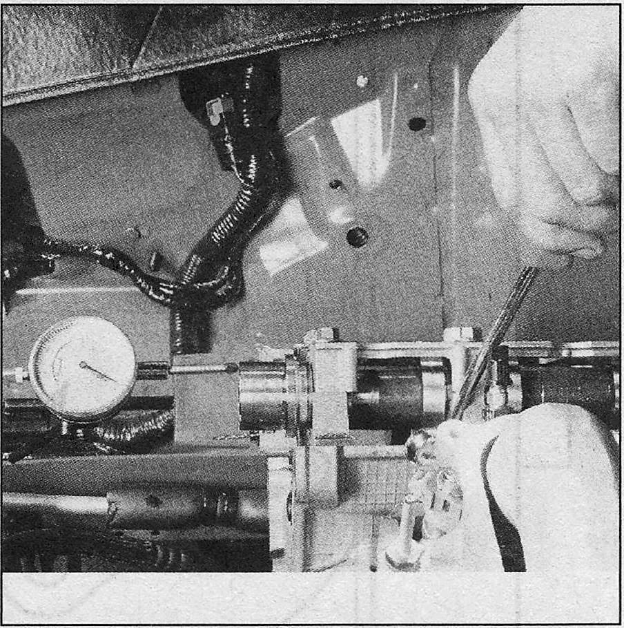
i.3 Camshaft end play can be checked by setting up a dial indicator off the front of the camshaft and prying the camshaft gently forward and back
3. Measure the thrust clearance (endplay) of the camshaft(s) with a dial indicator (see illustration). If the clearance is greater than the value listed in this Chapter’s Specifications, replace the camshaft and/or the cylinder head.
4. Hold the flats of the camshaft with a wrench while using a ratchet and socket to remove the VCT mounting bolts (see Timing chains, tensioners and sprockets – removal, inspection and installation). Note: If the VCT units are being removed from both cylinder banks, remove the right hand VCT units first.
5. Remove the VCT oil filter screens from the front of each camshaft. The filters must be replaced each time the VCT assembly has been removed.
6. Slide the VCT assemblies and secondary chain forward about 5/64-inch (2 mm).
7. Push down on the secondary timing chain tensioner until slack in the chain is felt then rotate the tensioner 90-degrees counterclockwise.
8. Slide the VCT assemblies and chain off of the camshafts as a unit.
9. Remove the larger camshaft cap (megacap) at the front first. Loosen and remove the remainder of the bearing cap bolts, 1/4-turn at a time, in the reverse of the tightening sequence (see illustration 20c), and remove the caps.
10. Lift the camshafts out of their bearing saddles and set the cams aside.
11. Keep the camshafts clean and mark them with paint to indicate left or right and intake or exhaust.
Inspection
i.12 Areas to look for excessive wear or damage on the camshafts are the bearing surfaces and the camshaft lobes
12. Visually examine the cam lobes and bearing journals for score marks, pitting, galling and evidence of overheating (blue, discolored areas). Look for flaking of the hardened surface of each lobe (see illustration). Inspect the bearing surfaces of the camshaft bearing caps for signs of excessive wear, damage or overheating.
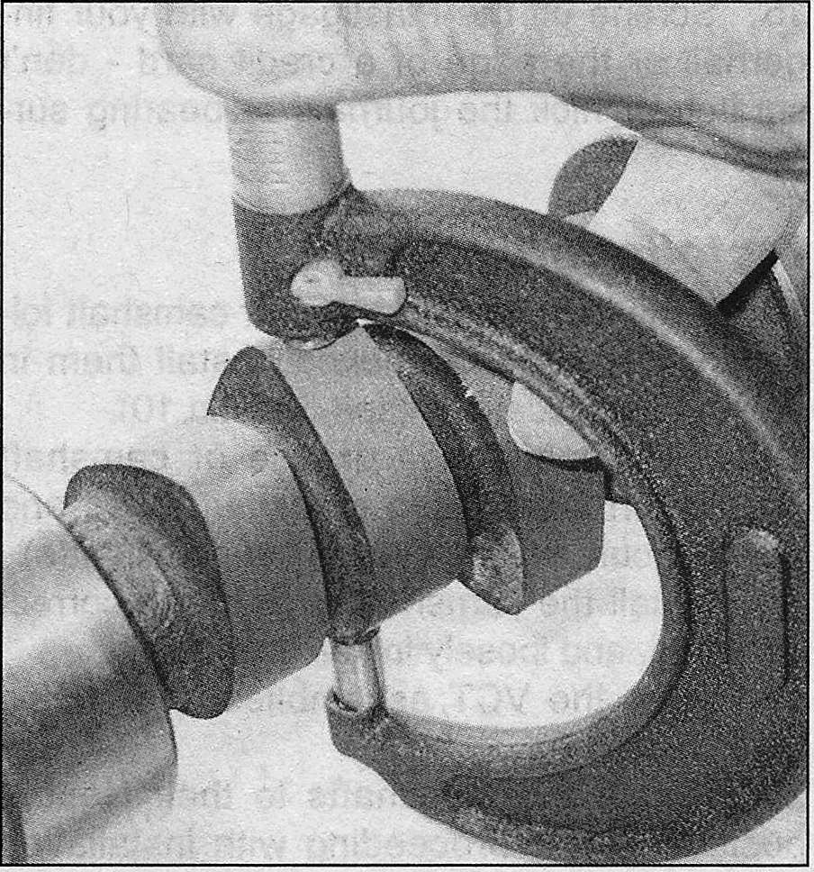
i.13a Measure the camshaft bearing journal diameter
i.13b Measure the camshaft lobe at its greatest dimension
i.13c Subtract the camshaft lobe diameter at its smallest dimension to obtain the lobe lift specification
13. Using a micrometer, measure the diameter of each camshaft journal and the lift of each camshaft lobe (see illustrations). Compare your measurements with the Specifications listed at the front of this Chapter, and if the diameter of any one of these is less than specified, replace the camshaft.
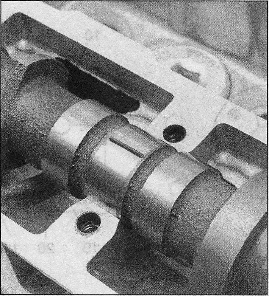
i.14a Lay a strip of Plastigage on each of the camshaft journals
i.14b Compare the width of the crushed Plastigage to the scale on the envelope to determine the oil clearance
14. Check the oil clearance for each camshaft journal as follows:
15. Scrape off the Plastigage with your fingernail or the edge of a credit card — don’t scratch or nick the journals or bearing surfaces.
Installation
16. If the lash adjusters and/or camshaft followers have been removed, install them in their original locations (see Roller followers and valve lash adjusters – removal, inspection and installation).
17. Apply moly-base grease or camshaft installation lube to the camshaft lobes and bearing journals, then install the camshaft(s).
18. Install the camshaft caps in the correct locations, and loosely install all the bolts.
19. Align the VCT assemblies and chains (see Timing chains, tensioners and sprockets – removal, inspection and installation).
i.20a These U-shaped slots in the face of the camshaft should be oriented like this (right [passenger’s- side] bank)
i.20b These U-shaped slots in the face of the camshaft should be oriented like this (left [driver’s-side] bank)
20. Rotate the camshafts to their Neutral position before proceeding with installation of the VCT assemblies and timing chains (see illustrations). Follow the bolt-tightening sequence (see illustration), and tighten the bolts to the torque listed in this Chapter’s Specifications.
21. Install the VCT assemblies and chains and timing chain(s) (see Timing chains, tensioners and sprockets – removal, inspection and installation).
22. The remainder of installation is the reverse of removal.


![Ford F150 V8 engine_Camshaft(s) - removal, inspection and installation _These U-shaped slots in the face of the camshaft should be oriented like this (right [passenger's- side] bank)](http://ford.car-owners-manual.com/img/f150_repair/img-2b/2B-12-1.JPG)
![Ford F150 V8 engine_Camshaft(s) - removal, inspection and installation _These U-shaped slots in the face of the camshaft should be oriented like this (left [driver's-side] bank)](http://ford.car-owners-manual.com/img/f150_repair/img-2b/2B-12-2.JPG)