Instrument panel — removal and installation Ford F150
Warning: The models covered by this manual are equipped with a Supplemental Restraint System (SRS), more commonly known as airbags. Always disable the airbag system before working in the vicinity of any airbag
system component to avoid the possibility of accidental deployment of the airbags, which could cause personal injury (see Chassis electrical system).
Caution: This is a difficult procedure for the home mechanic. There are many hidden fasteners, difficult angles to work in and many electrical connectors to label and disconnect/ connect. We recommend that this procedure be done only by an experienced do-it-yourselfer.
Note: During removal of the instrument panel, make careful notes of how each piece comes off, where it fits in relation to other pieces and what holds it in place. If you note how each part is installed before removing it, getting the instrument panel back together again will be much easier. Label the electrical connectors and keep track of where each fastener belongs for installation.
1. Disconnect the cable from the negative battery terminal (see Battery and battery tray – removal and installation). Turn the front wheels to the straight-ahead position and lock the steering column.
2. Remove the A-pillar trim panels (see illustrations) and disconnect the electrical connector to the tweeters (see Chassis electrical system), if equipped.
.2a Remove the screw covers and A-pillar mounting screws…
.2b…then pull the panel off of the A-pillar and disconnect the tweeter electrical connector (if equipped)
3. If equipped, remove the center console (see Center console – removal and installation).
4. Remove the steering wheel (see Suspension and steering systems).
5. Remove the knee bolster (see Dashboard trim panels – removal and installation).
6. Remove the instrument panel end caps (see illustration).
.6 Use a flat-bladed tool or trim stick to remove the instrument panel end caps
7. Remove the scuff plate from each door opening (see illustration).
.7 Carefully pry up and remove the scuff plates
8. Remove the side kick panels at each end (see illustrations) and pull the weather stripping off the front of each door opening.
.8a Pry up the rear of the kick panel…
.8b. . . then pull the kick panel off
9. Remove the front driver and passenger seats, then the front center seat (see Seats – removal and installation).
10. Remove the floor console (see Center console – removal and installation), if equipped.
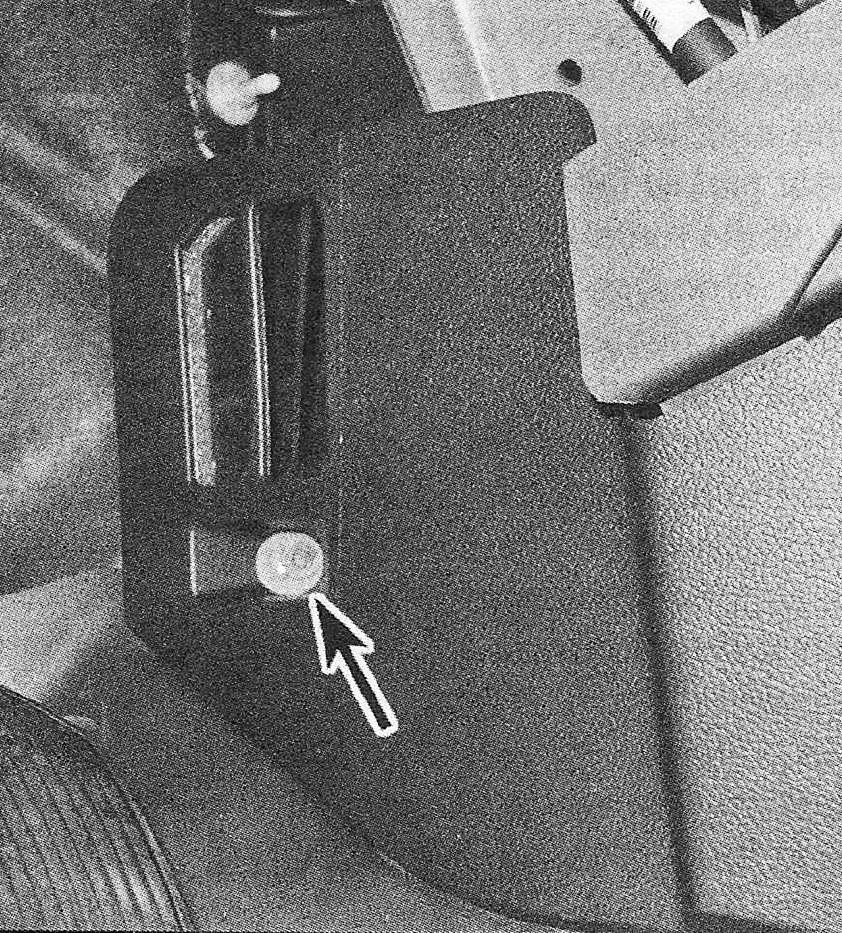
11. On models without floor consoles, remove the lower trim panel (see illustra tions).
.11a Remove the lower trim panel fastener…
.11b…then pull out the trim panel to release it from the clips
12. On models equipped with a steering column mounted shift lever, remove the steering column covers (see Steering column covers – removal and installation).
13. Remove the steering column support (see illustration).
.13 Steering column support plate bolt locations
14. Remove the select lever cable mounting bolt then pop the end of the cable off of the selector ballstud (see illustration). Separate the shift cable from the bracket by lifting the rear plastic tabs with a screwdriver and sliding it off the metal bracket.
.14 Remove the select lever cable mounting bolt (1) then gently pop the cable end off the selector ballstud (2) with a screwdriver
15. Remove the floor covering fasteners, where necessary, and pull the covering back (see illustrations).
.15a Pull the floor covering back from the left…
.15b…and right side
16. If equipped, remove the plastic retainers for the floor ducts and remove the ducts.
17. Remove the wiring harness retainers along the floorboard (see illustration). Also disconnect the electrical connectors, where equipped.
.17 Release the plastic harness retainers along the floorboard
18. Remove the plastic push pin retainers on the insulator panel under the glove-box and remove the insulator (see Dashboard trim panels – removal and installation).
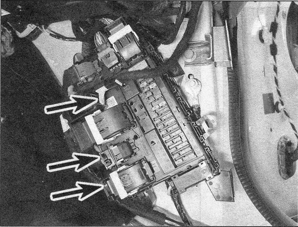
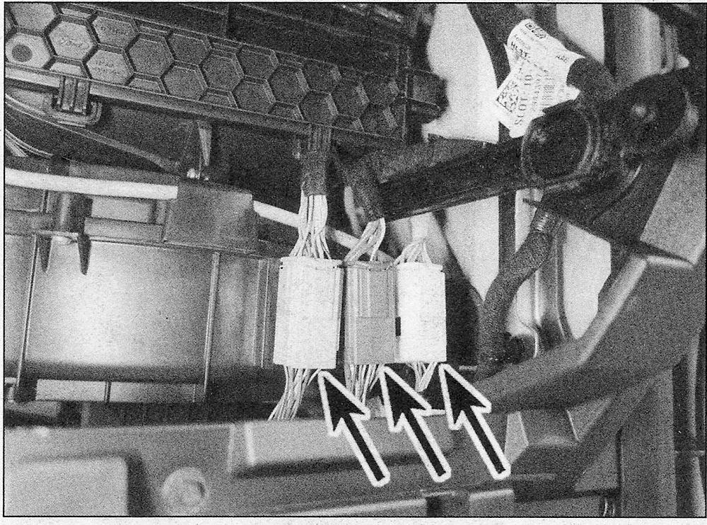
19. Disconnect the instrument panel electrical connectors (see illustrations).
.19a Disconnect these electrical connectors from the right side kick panel area…
.19b…and from behind the glove box…
.19c. . .and at the left side of the glove box opening, remove the electrical connectors and instrument panel mounting bolt (1)…
.19d…then disconnect the electrical connectors from the left side kick panel.
Note: A number of electrical connectors must be disconnected in order to remove the instrument panel. Most are designed so that they will only fit on the matching connector (male or female), but if there is any doubt, mark the connectors with masking tape and a marking pen before disconnecting them.
20. Remove the pinch bolt and disconnect the upper steering column shaft (see illustration). Check the steering column removal Warnings in Steering column – removal and installation.
.20 Remove the upper steering column shaft pinch bolt
21. Remove the access panels from the top of the dashboard and remove the mounting bolts (see illustrations).
.21a Remove the access panel from each side of the dashboard…
.21b…and remove the instrument panel top mounting bolts (viewed from the outside looking through the windshield)
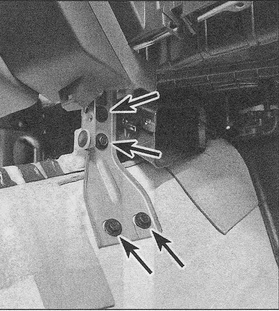
22. Remove the fasteners securing the instrument panel (see illustrations).
.22a Remove the fasteners from the right side…
.22b… and the left side…
.22c… then remove the instrument panel left side center bracket fasteners…
.22d… and right side center bracket fasteners
23. Pull the instrument panel towards the rear of the vehicle and disconnect any remaining electrical connectors interfering with removal, if necessary. Make absolutely sure that all the necessary electrical connectors are disconnected.
24. Once all the electrical connectors have been confirmed to be disconnected, rotate the instrument panel assembly to be face-down, then carry it out through the driver’s door opening.
25. Installation is the reverse of removal.


