Suspension and steering systems Ford F150
Front suspension
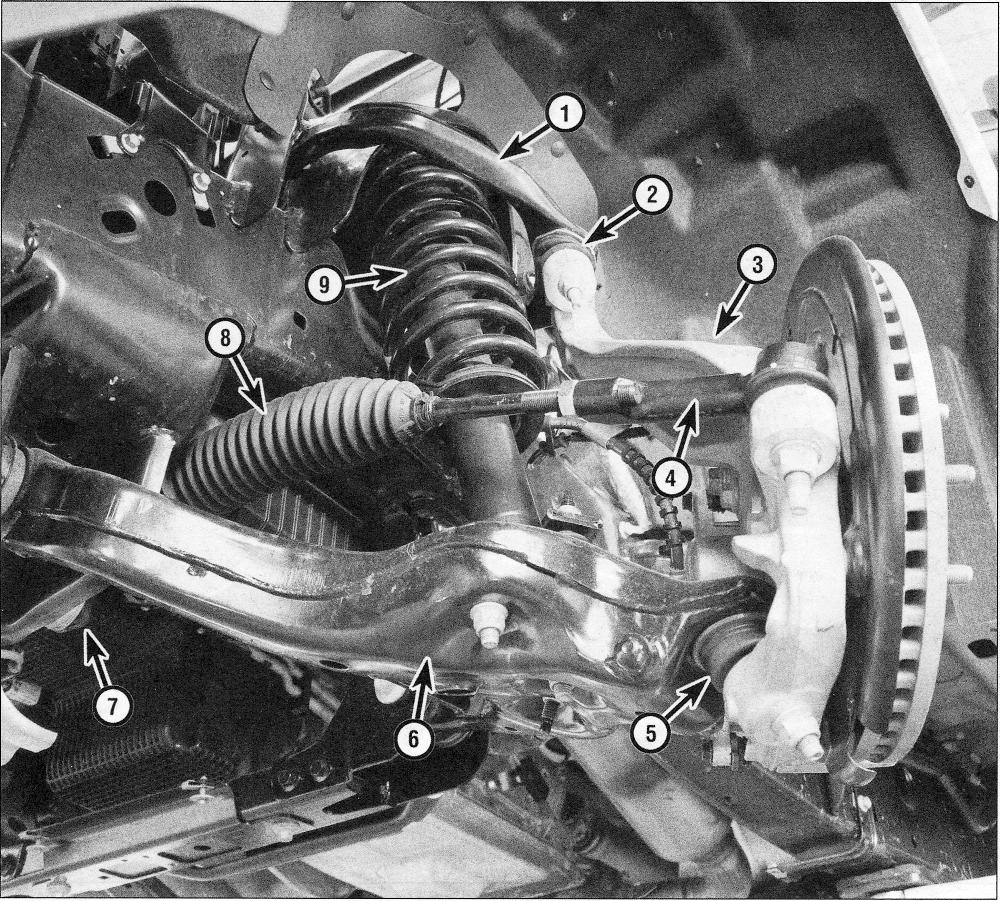
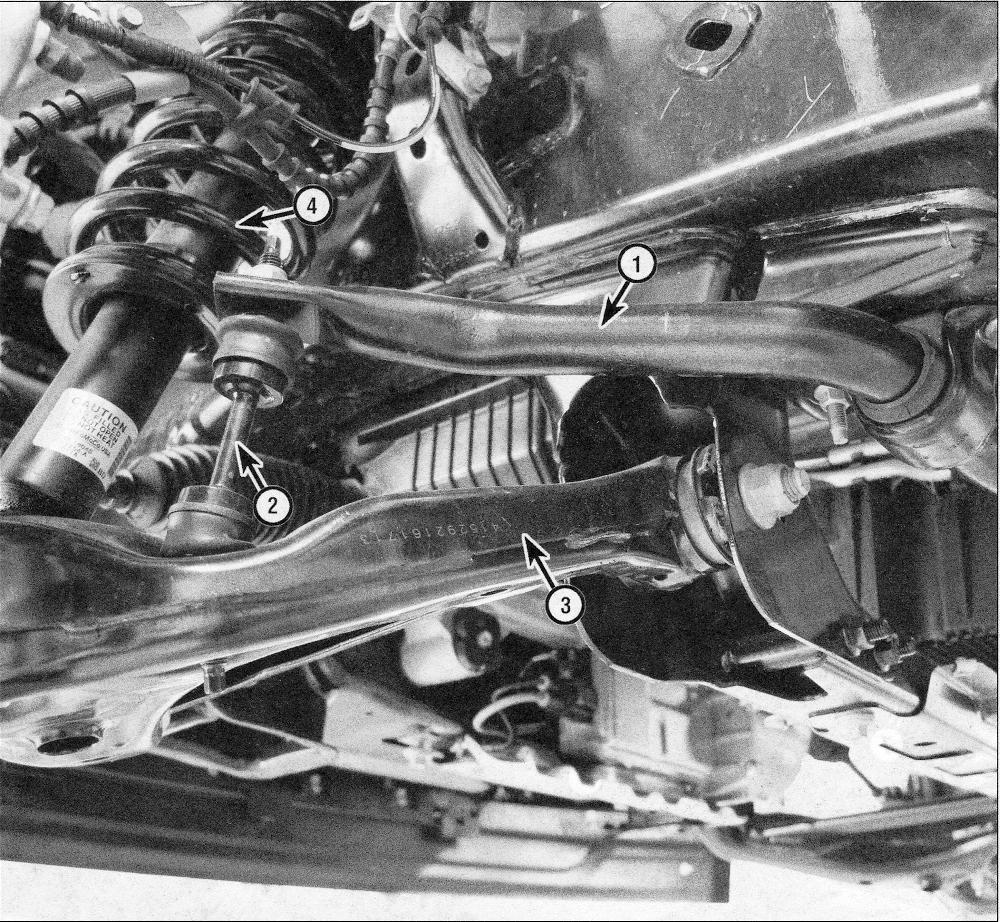
1. The front suspension system is fully independent (see illustrations). The steering knuckles are connected to the upper and lower control arms by balljoints. The control arms are bolted to the frame. The shock absorbers and coil springs are integral assemblies (coil-over shock); the upper ends are bolted to the frame and the lower ends are bolted to the lower control arms. All models use a front stabilizer bar to reduce body roll during cornering.
.1a Front suspension and steering components — front view (2WD model shown, 4WD model similar)
1. Upper control arm
2. Upper balljoint
3. Steering knuckle
4. Tie-rod end
5. Lower balljoint
6. Lower control arm
7. Steering gear
8. Steering gear boot
9. Shock absorber/coil spring assembly
.1b Front suspension components — rear view
1. Stabilizer bar
2. Stabilizer bar link
3. Lower control arm
4. Shock absorber/coil spring assembly
Rear suspension
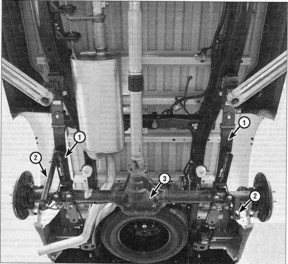
2. The rear suspension uses shock absorbers and leaf springs (see illustration). The forward end of each spring is attached to a bracket on each frame rail. The rear of each spring is shackled to a bracket on the side of the frame rail.
.2 Rear suspension components
1. Leaf springs
2. Shock absorber
3. Rear axle housing
Steering
3. All models are equipped with electric power-assisted rack-and-pinion steering systems. The steering gear is bolted to the crossmember and is connected to the steering knuckles by a pair of tie-rods.
4. The EPAS (Electronic Power Assist Steering) system takes the place of the conventional hydraulic power steering system. The EPAS communicates by way of a PSCM (Power Steering Control Module) on a high speed data line with various other modules. The PSCM sends these signals to the EPAS and operates the reversible electric motor at various torque and reaction levels for the different driving conditions and road hazards.
5. The PSCM compensates for the speed as well as pull or drift experienced in normal driving and maintains steering stability. Along with drift control, the electronic steering system allows for greater parking lot maneuverability by increasing the torque-to-turn ratio at slow speeds as well as decreasing the turning force for straight ahead highway driving.
Lane Keeping System (LKS)
6. LKS (Lane Keeping System) is integrated with the EPAS, which uses a forward facing camera to evaluate the road lines and edges and helps to maintain the vehicle within those barriers. The steering wheel will vibrate and a visual message is sent to the instrument cluster if the vehicle veers to one side or the other when the system is activated.
Precautions
7. Frequently, when working on the suspension or steering system components, you may come across fasteners which seem impossible to loosen. These fasteners on the underside of the vehicle are continually subjected to water, road grime, mud, etc., and can become rusted or frozen, making them extremely difficult to remove. In order to unscrew these stubborn fasteners without damaging them (or other components), be sure to use lots of penetrating oil and allow it to soak in for a while. Using a wire brush to clean exposed threads will also ease removal of the nut or bolt and prevent damage to the threads. Sometimes a sharp blow with a hammer and punch is effective in breaking the bond between a nut and bolt threads, but care must be taken to prevent the punch from slipping off the fastener and ruining the threads. Heating the stuck fastener and surrounding area with a torch sometimes helps too, but isn’t recommended because of the obvious dangers associated with fire. Long breaker bars and extension, or cheater, pipes will increase leverage, but never use an extension pipe on a ratchet — the ratcheting mechanism could be damaged. Sometimes, turning the nut or bolt in the tightening (clockwise) direction first will help to break it loose. Fasteners that require drastic measures to unscrew should always be replaced with new ones.
Note: Plain water poured over a rusty nut and allowed to soak will sometimes soften the rust between the threads better than penetrating oils can. It doesn’t work every time, however it might be a good first effort before resorting to the oils or the hammer and chisel.
Note: Since most of the procedures that are dealt with in this Chapterinvolve jacking up the vehicle and working underneath it, a good pair of jackstands will be needed. A hydraulic floor jack is the preferred type of jack to lift the vehicle, and it can also be used to support certain components during various operations.
Warning: Never, under any circumstances, rely on a jack to support the vehicle while working on it. Also, whenever any of the suspension or steering fasteners are loosened or removed they must be inspected and, if necessary, replaced with new ones of the same part number or of original equipment quality and design. Torque specifications must be followed for proper reassembly and component retention. Never attempt to heat or straighten suspension or steering components. Instead, replace bent or damaged parts with new ones.
Shock absorber/coil spring (front) – removal, component replacement and installation
Stabilizer bar and bushings – removal and installation
Steering knuckle – removal and installation
Upper control arm – removal and installation
Lower control arm – removal and installation
Hub and bearing assembly – replacement
Balljoints – check and replacement
Shock absorbers (rear) – removal and installation
Leaf springs – removal and installation
Steering wheel – removal and installation
Steering column – removal and installation
Tie-rod ends – removal and installation
Steering gear boots – replacement
Steering gear – removal and installation
Wheels and tires – general information
Wheel alignment – general information


